2d drawing into 3d modeling blueprints
Using 2nd to 3D method to create solid 3D objects and openings in Rhino
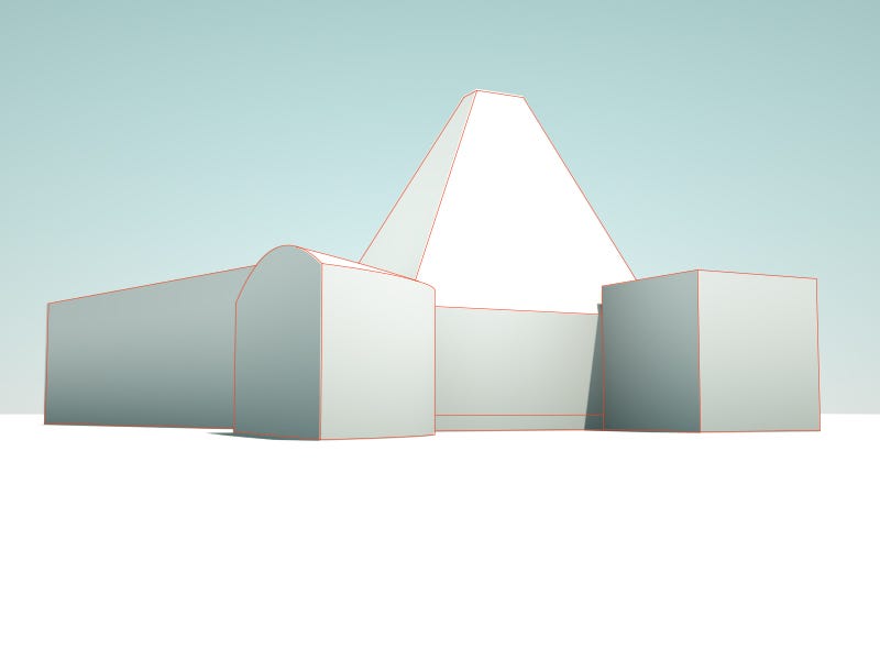
The tutorial demonstrates different 2d to 3D methods to create 3D solid object in Rhino. Too some different ways to handle openings on the building are included in the demonstration. Past going through this tutorial we are able to build the basic frame of the building model. The case model used in this tutorial is Winton Invitee House.
i. How to create the 2D reference geometry?
1.1 Use "picture frame" control to import the reference prototype and use "calibration 2D" control to adjust it to the right calibration.
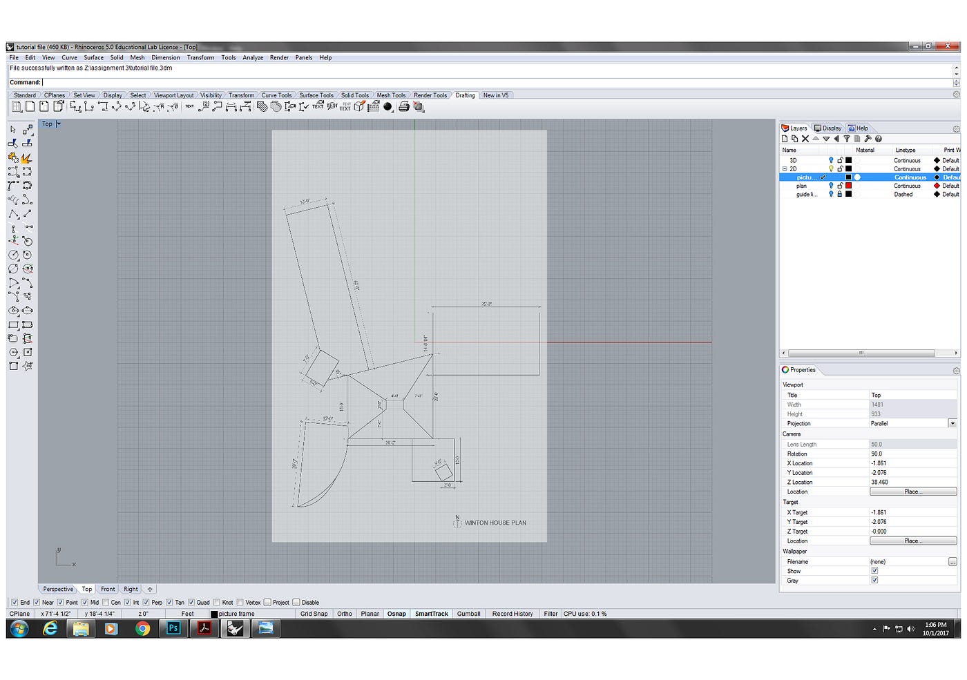
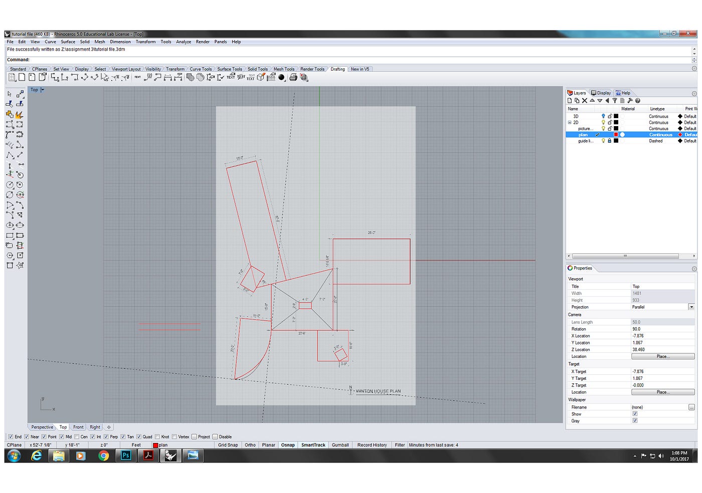
i.2 Add a layer named "2d" and add sub-layer named "plan". On this layer, trace the plan by using the basic 2D drafting commands ("line", "polyline", "rectangle", "interpCrv" "move", "rotate", etc.).
2. How to move different second flooring levels into proper tiptop locations?
two.one Select target 2D objects, use "movement" command, and fix "vertical" choice to "yep". So blazon in the altitude to move selected objects vertically.
2.2 We can also use "re-create" command to copy and move target second objects. Similar to "move" command, set "vertical" to "yes", then type in the distance to re-create and move.
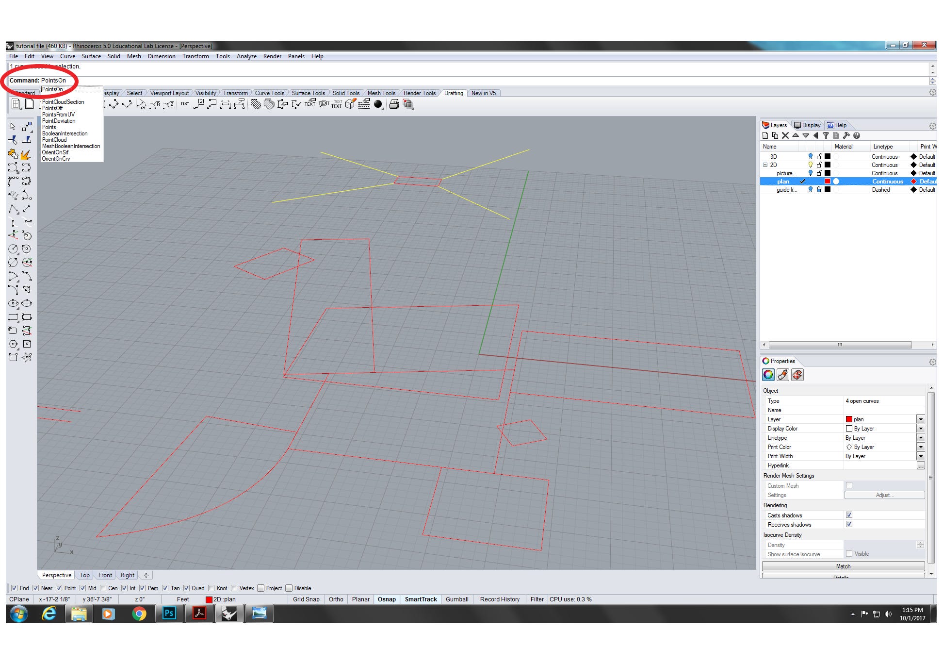
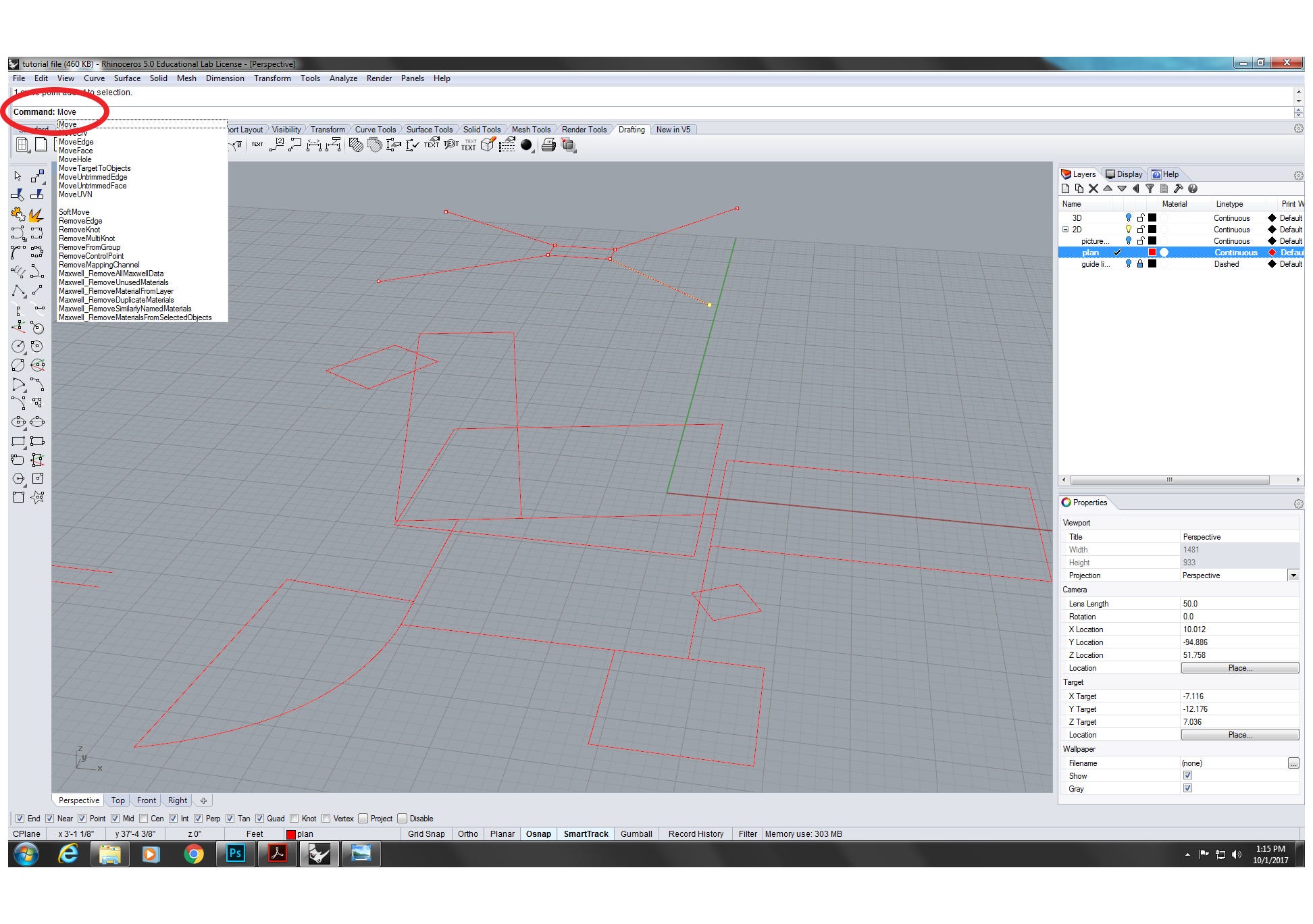
ii.3 In lodge to create 2D reference objects in 3D infinite, we tin can select target objects and type in command "pointson" to turn on the points on the selected objects. Then select target points and use "movement" control to create the 2d reference objects (the pyramid rooftop in the Winton Guest House case).
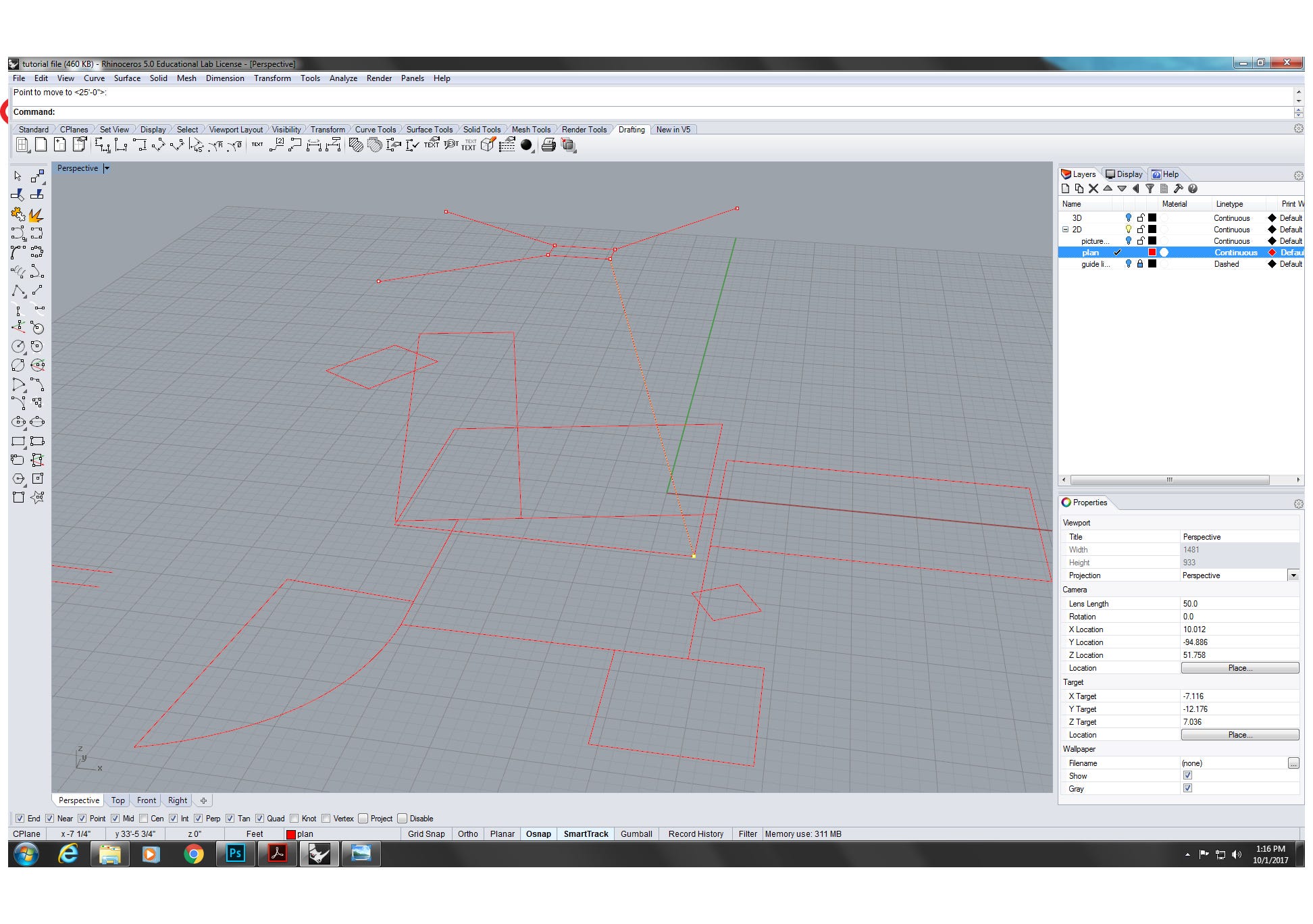
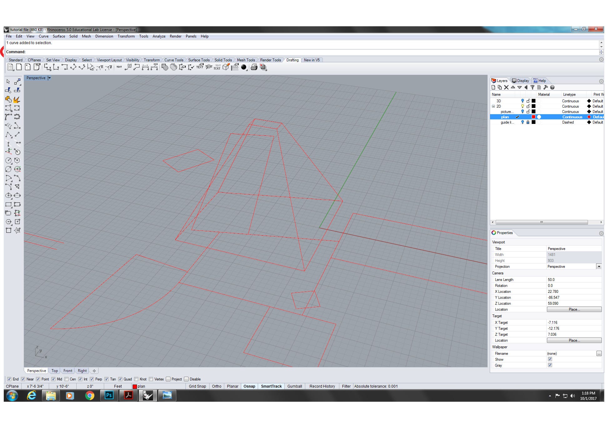
three. How to extrude 3D geometry?
3.1 The outset methods to create 3D geometry is to create 2D surface and use extrusion. Use "SrfPt" control, follow the commands. Then use "ExtrudeSrf" control, set the "soild" choice to "yes" and type in the extrusion distance to finish.
3.2 The second way to create 3D geometry is creating different surfaces in 3D space, then joining them into one solid 3D object. Firstly, explode all 2d geometry shapes into individual line. For the lines on the same plain to generate surface, employ the control "PlanarSrf". For the lines doesn't on the same obviously, employ the command "EdgeSrf". After generating all the surfaces, select them and click on the "Join" button to join them into 1 solid 3D object.
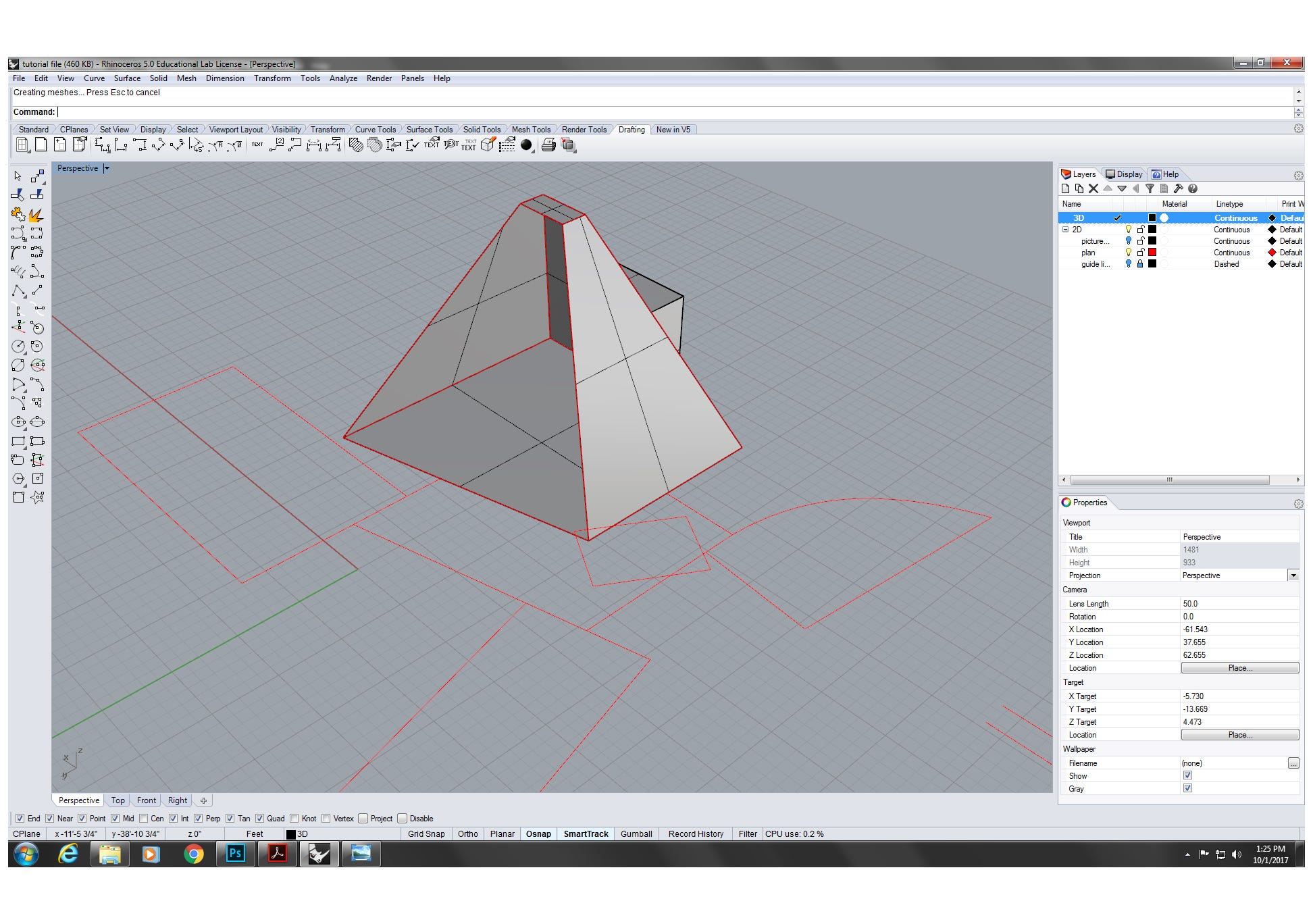
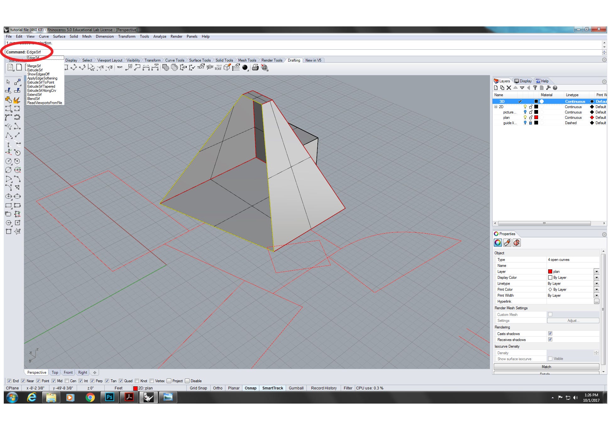
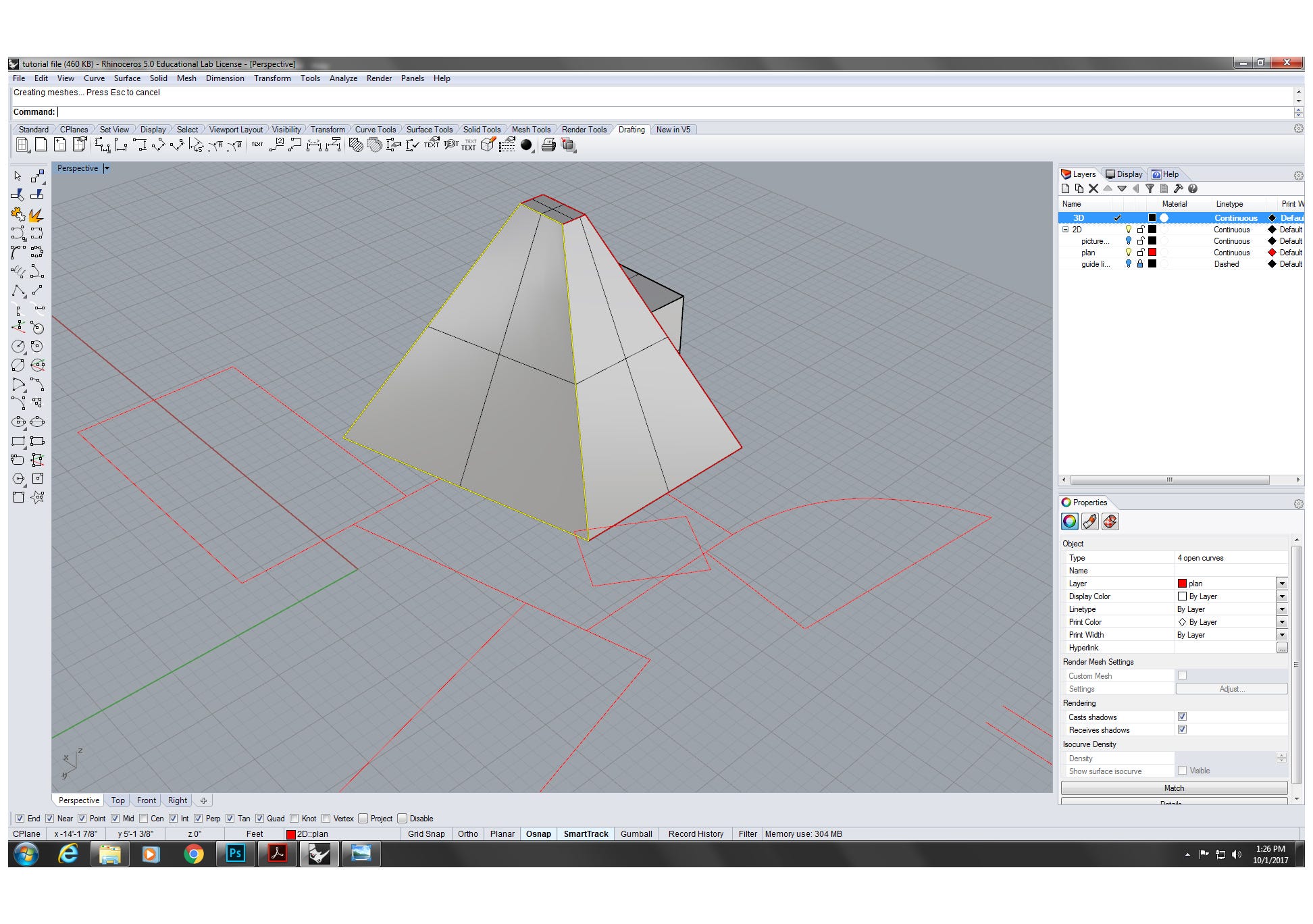
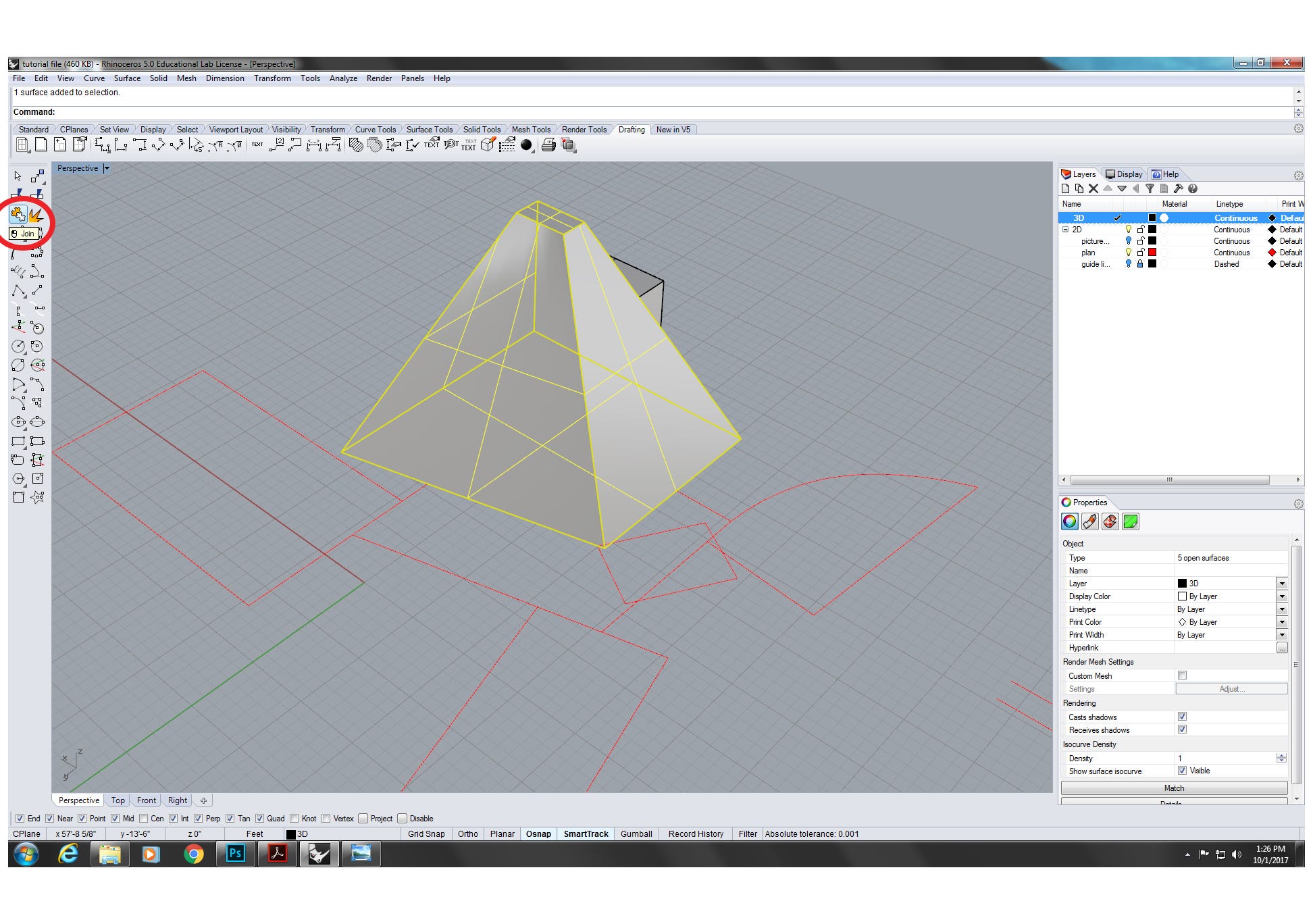
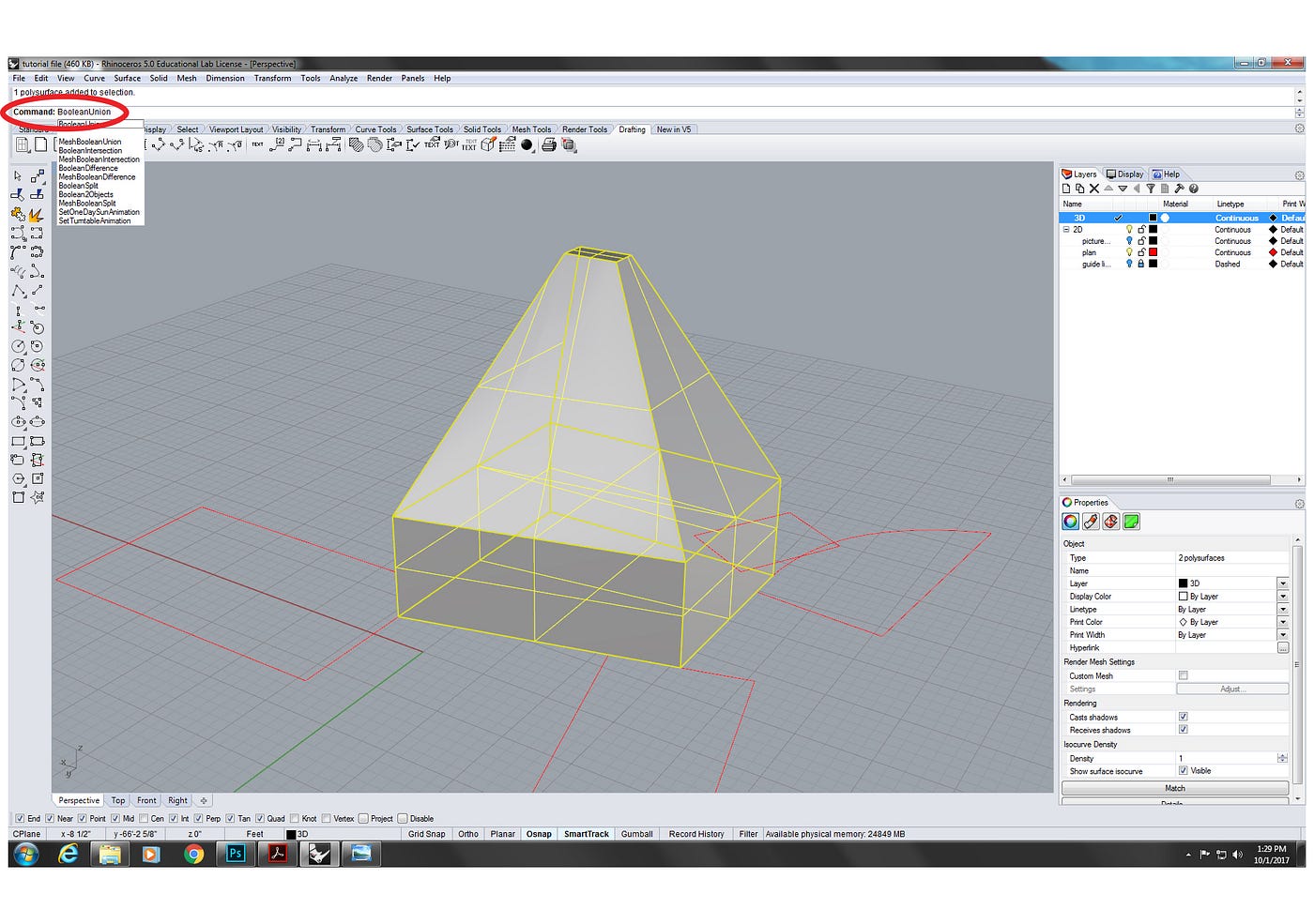
iii.iii For two solid 3D objects, we tin employ "BooleanUnion" command to join them into one solid 3D object.
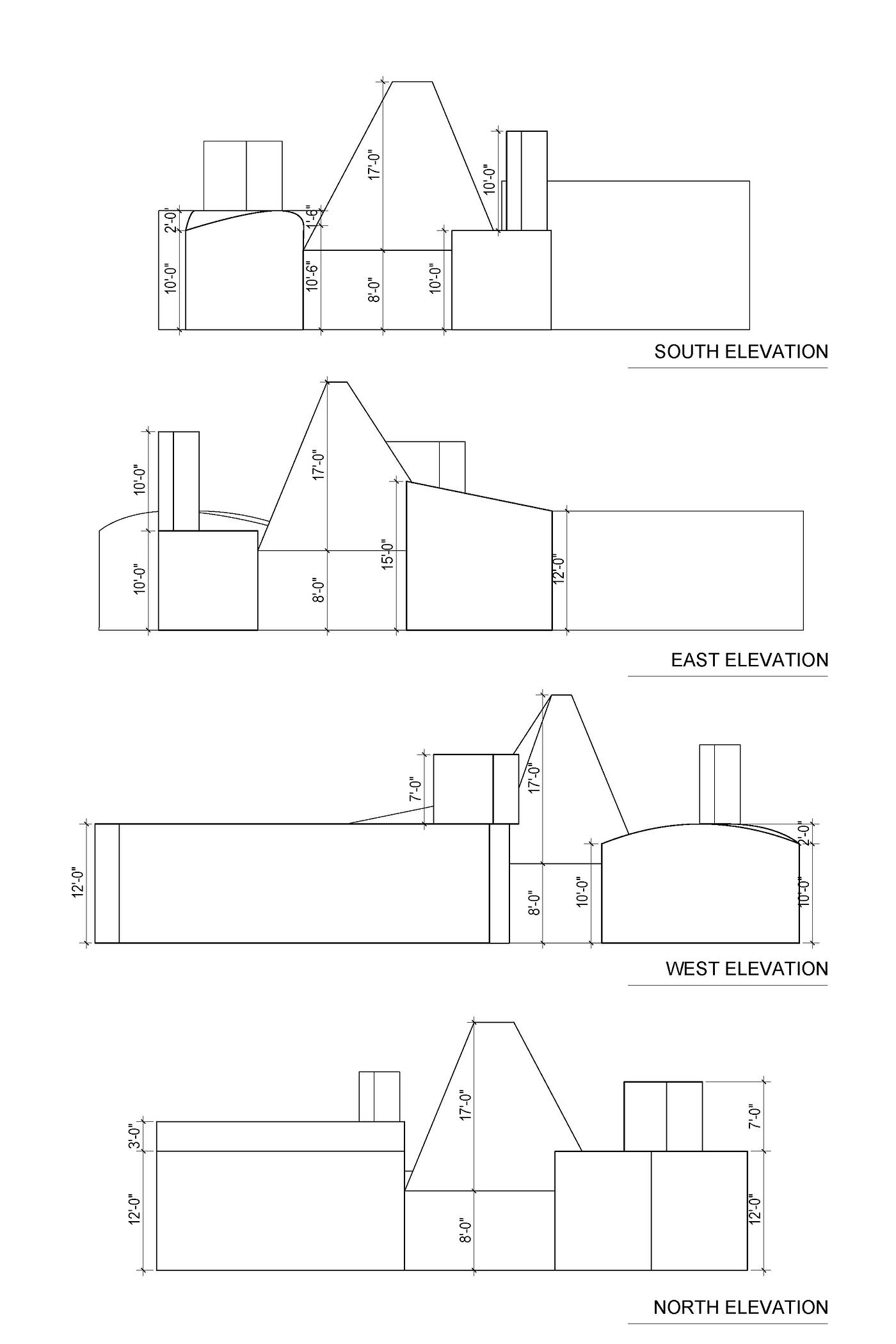
three.4 The third style to create complicate 3D geometry is using two objects with the "trim" command. In the example, in order to create the curved rooftop, based on the top drawing, firstly we need to build a simple 3D geometry past "PlanarSrf" and "ExtrudeSrf" control. And then utilize the reference dimension to depict the arc by " interpCrv " command. In order to motion the arc to the target 3D location, employ "Indicate" command to describe three target points. Then use "Orient3Pt" control and follow the commands to move the arc to the target location. The adjacent step is to copy the bottom lines and curves to the altitude that they can meet the arc. Utilize the "EdgeSrf" command with the arc and lines to generate a curving surface. Apply the surface as a reference with the "Trim" control to trim the 3D geometry, then bring together them into one solid 3D object.
4. How to handle openings such equally punctures, windows, doors, etc.?
four.one Nosotros tin utilize "crush" command to hollow a solid closed 3D object. Type in "vanquish" control and fix the "thickness" to a proper number. Then select the face to vanquish from.
4.2 For the building floor we can employ "PlanarSrf" to create a surface at the bottom of the shelled object, and use "ExtrudeSrf" to add the thickness to the floor.
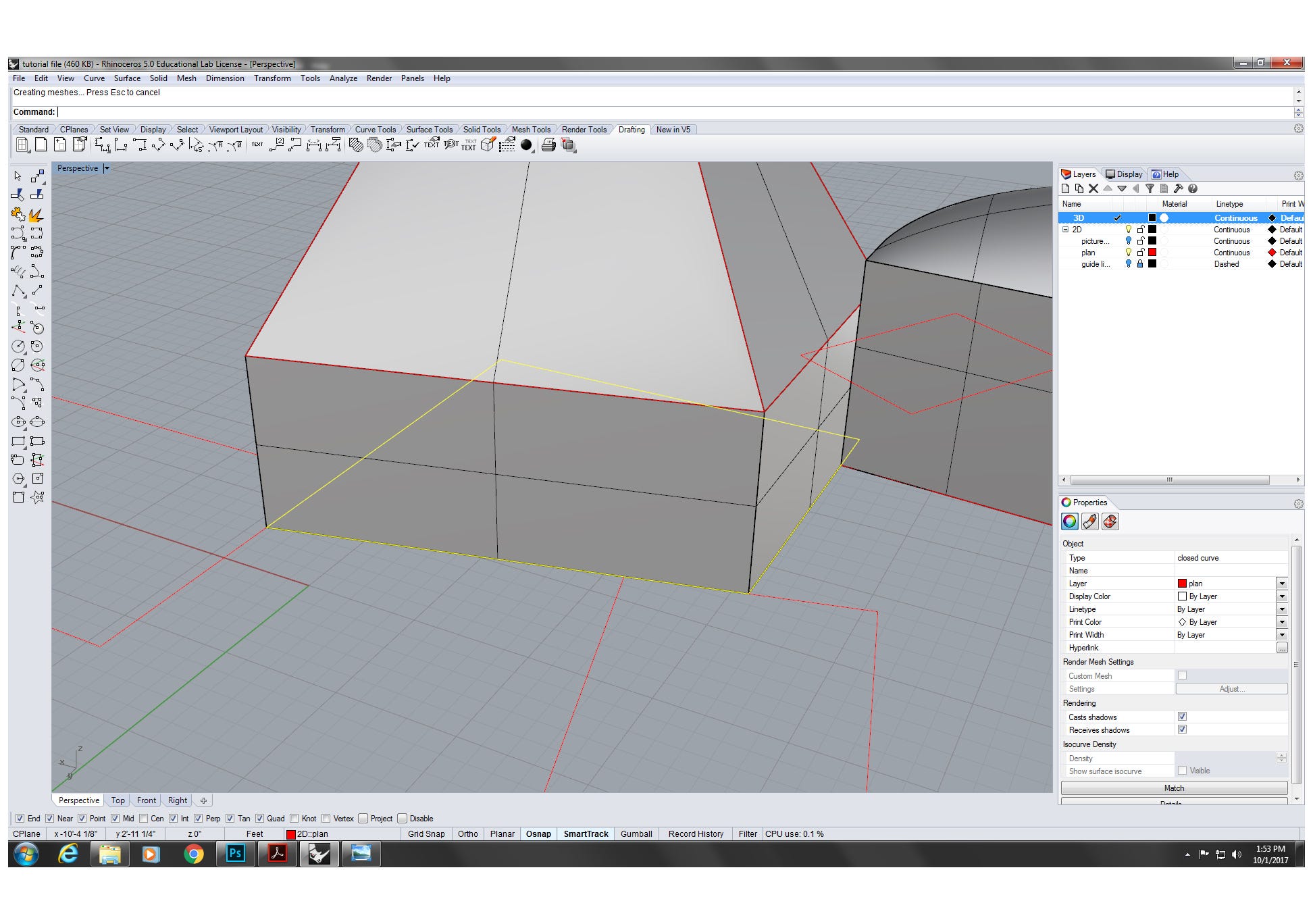
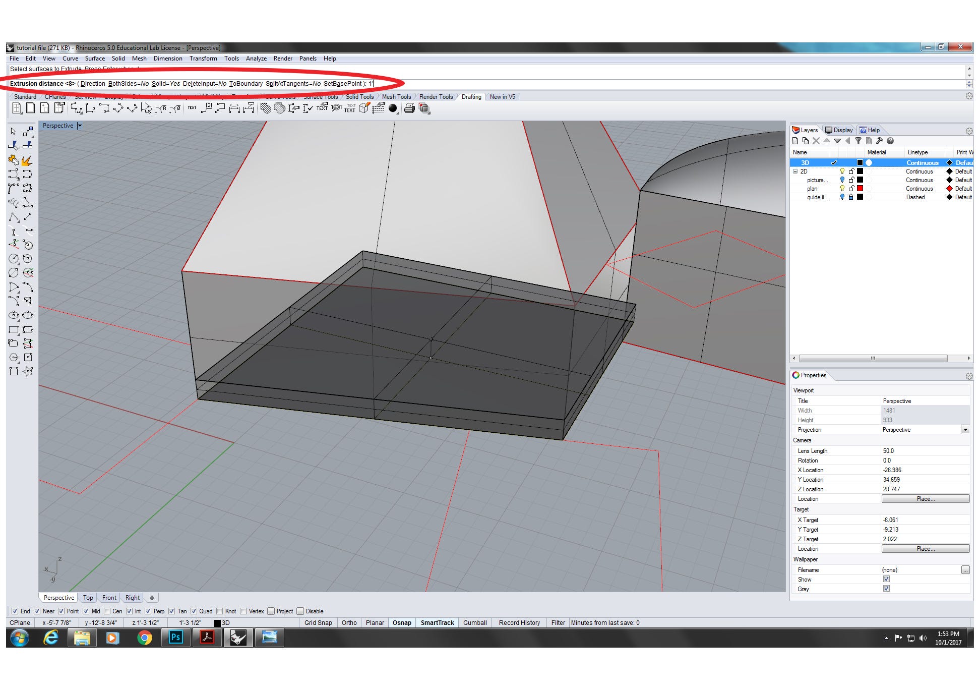
four.iii In order to create the door opening on the edifice, use "rectangle" and 'PlanarSrf' command to create a surface. Then utilise "Orient3Pt" control to move the surface to the target location on the building. By using "ExtrudeSrf" with the "BothSides" selection on "yes", we tin add thickness to the door. And so nosotros can use "BooleanDifference" control to create the door opening on the building, A(edifice) minus B(door).
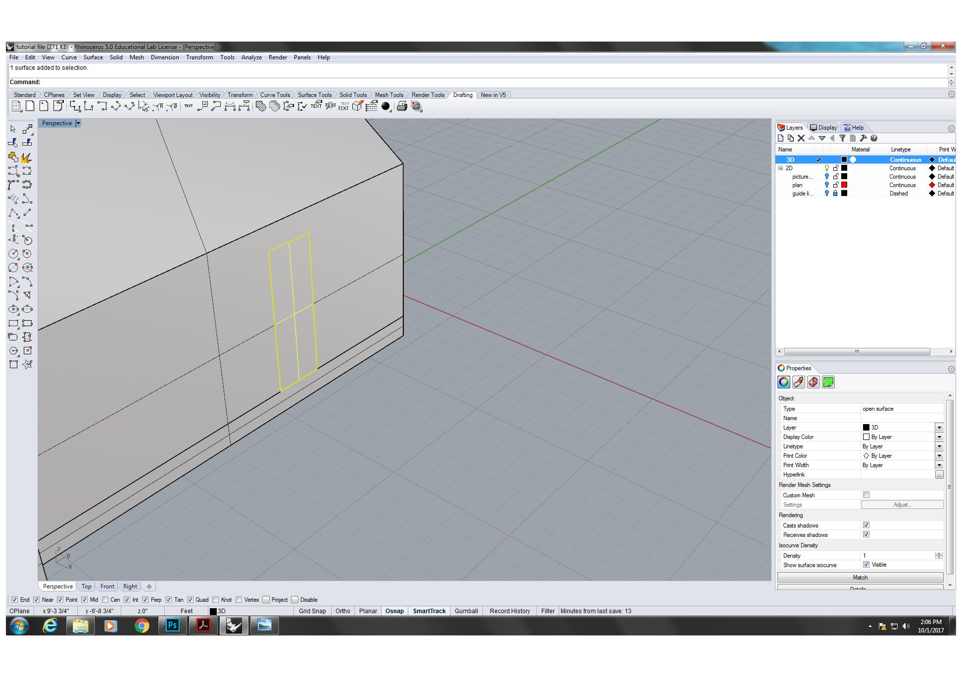
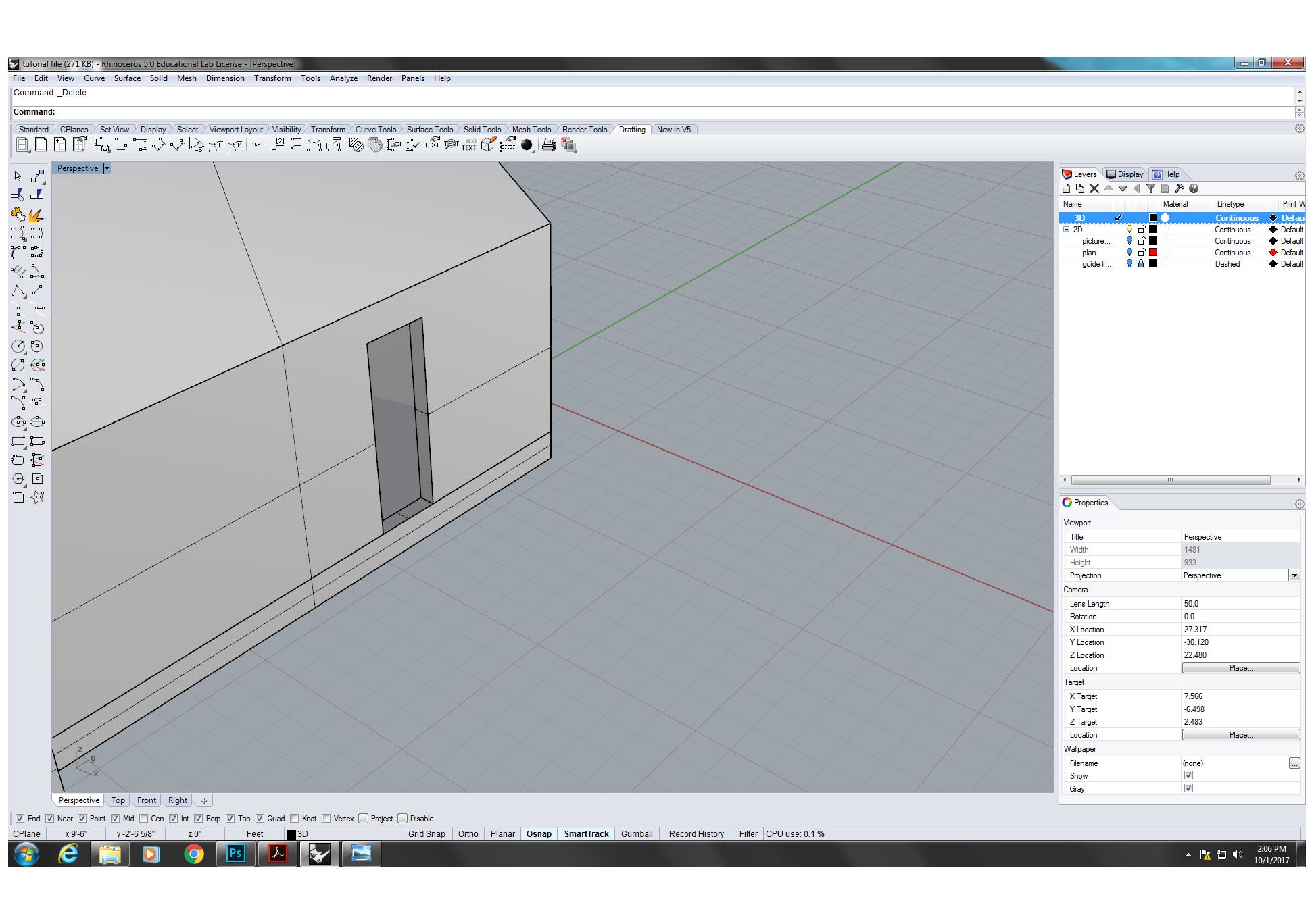
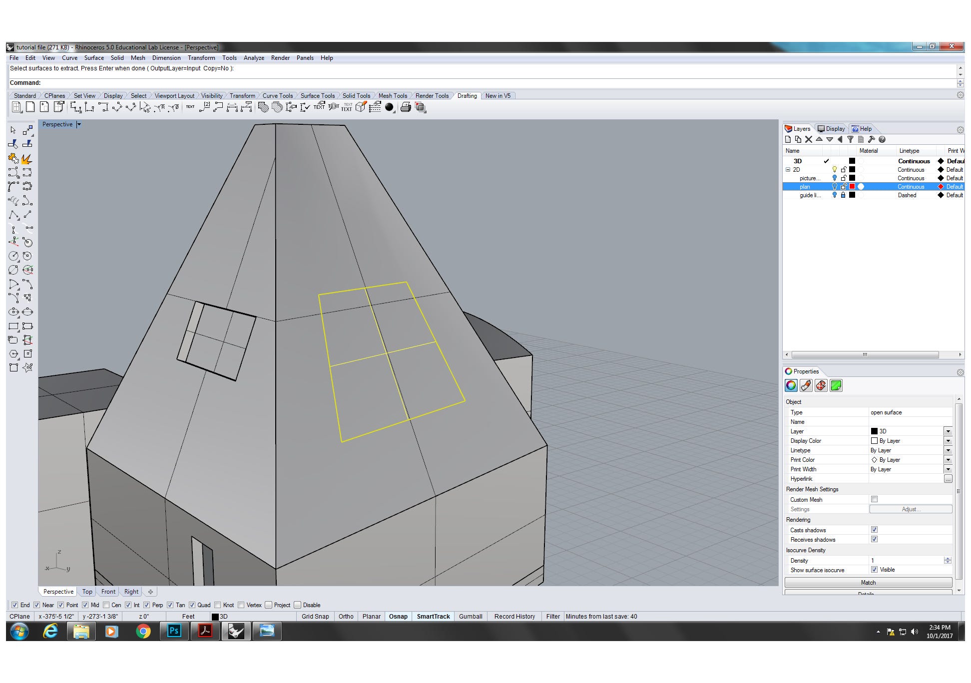
4.4 For the window on the angled confront, we can repeat the aforementioned steps that we creating the door. In order to create opening, we tin also use "ExtractSrf" instead of "ExtrudeSrf". Then utilise "BooleanDifference" to create the opening. To add the thickness to the window drinking glass, we can use "OffsetSrf" command. Follow the commands, set the direction and type in the proper distance to showtime.
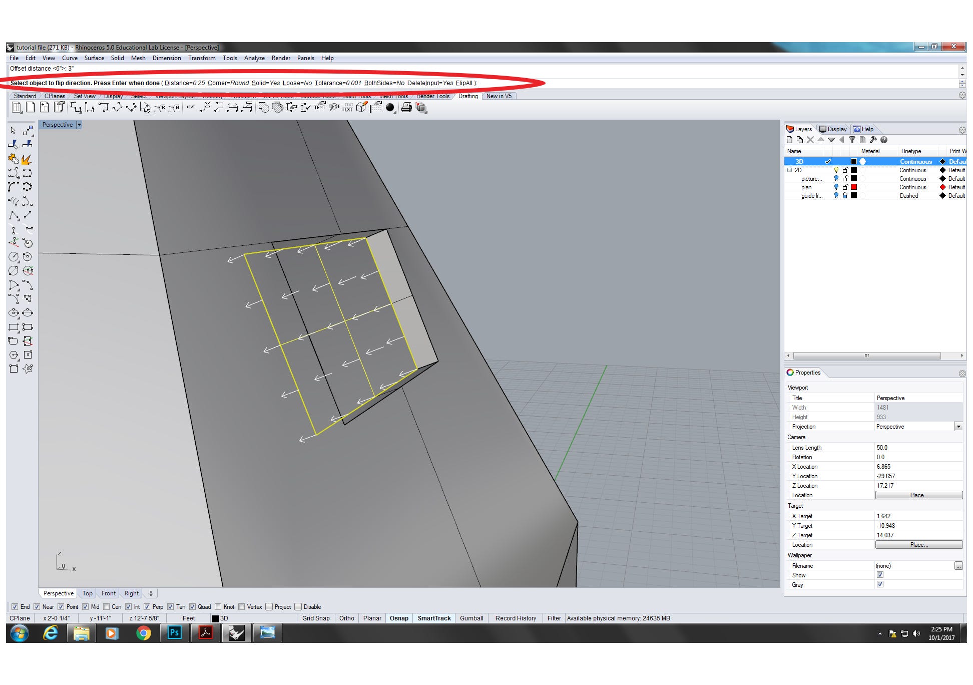
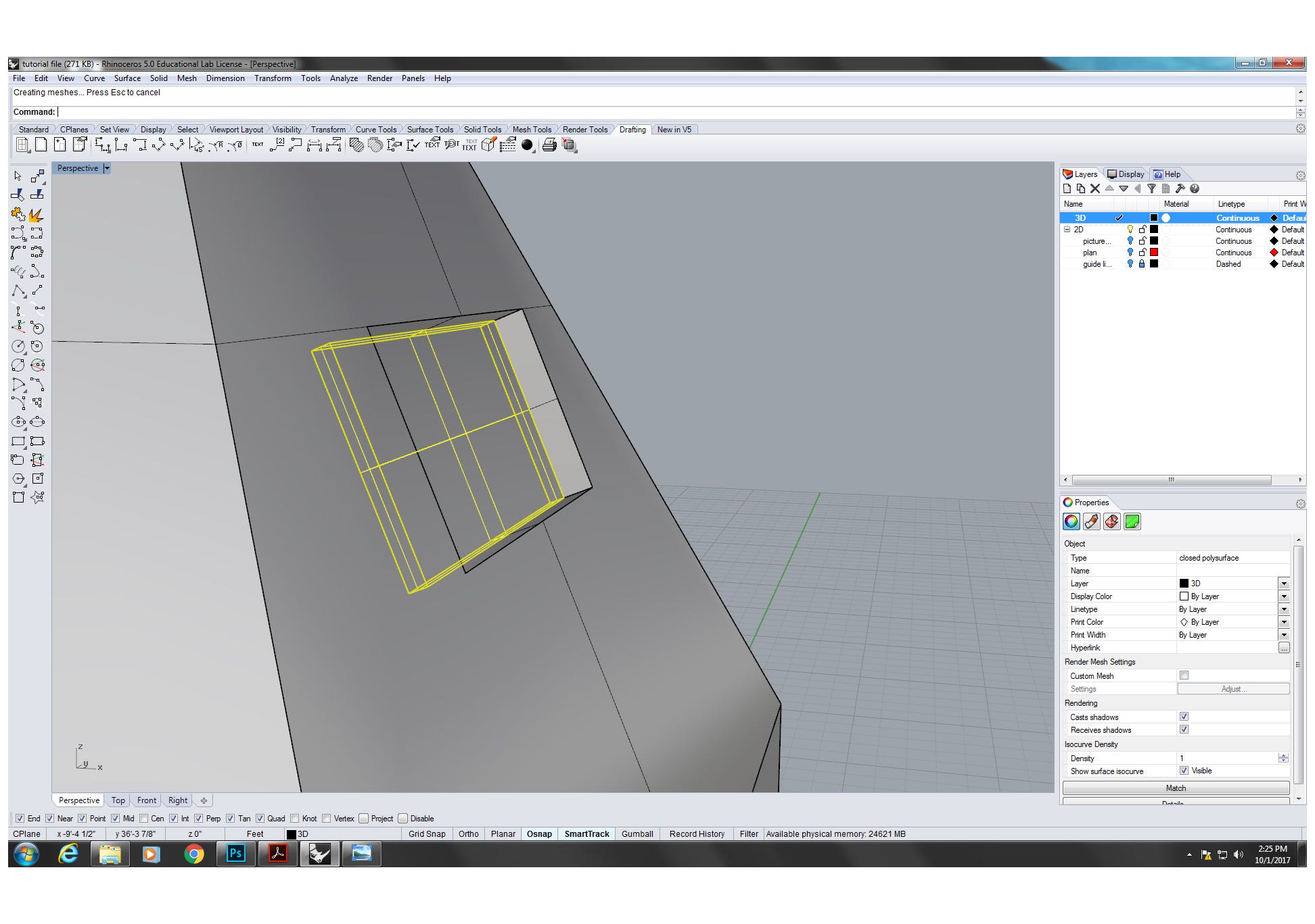
4.5 For the opening on the face up that is not on the same plain in 3D infinite, we can use "ExtractIsocurve" to offset all the curves on the face (ready "U" to "V" to change direction of the offsetting). And so trim the starting time curves and use "EdgeSrf" to generate a new surface. The process to create opening and add thickness is the same every bit the department iv.iv above.
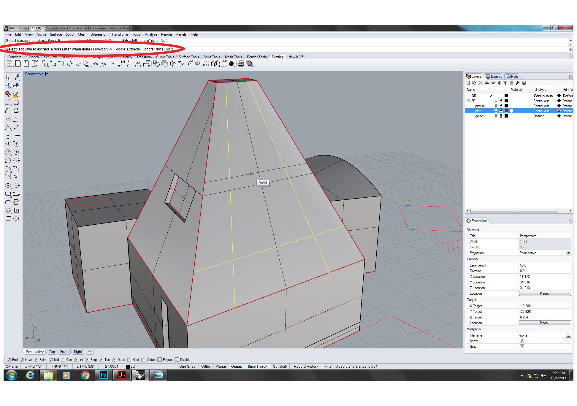
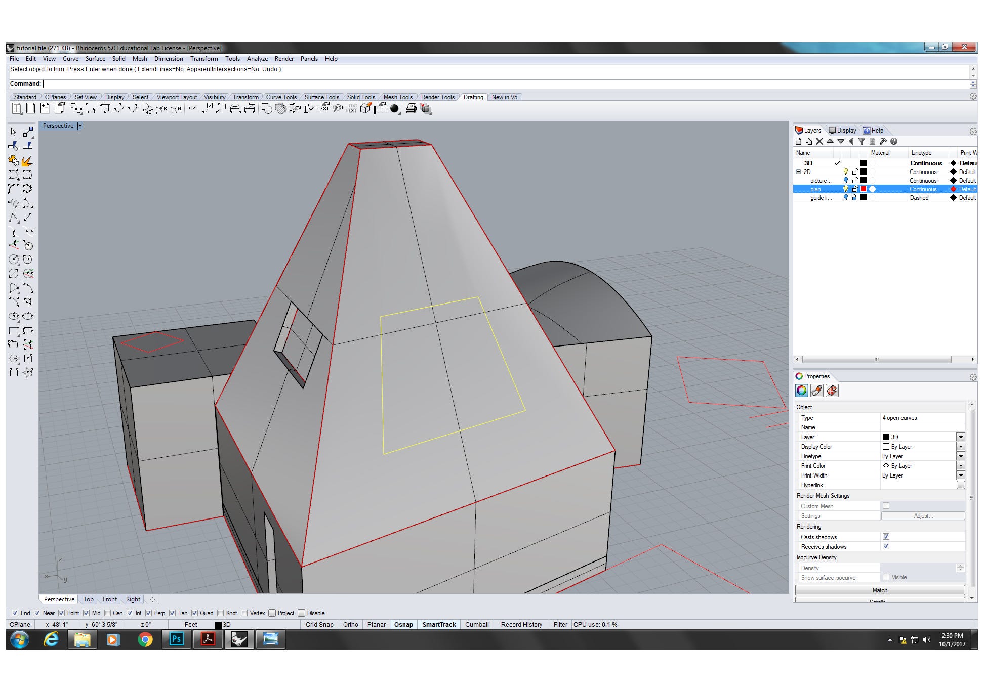
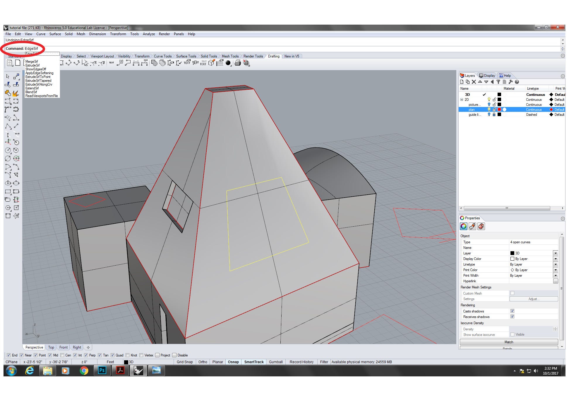
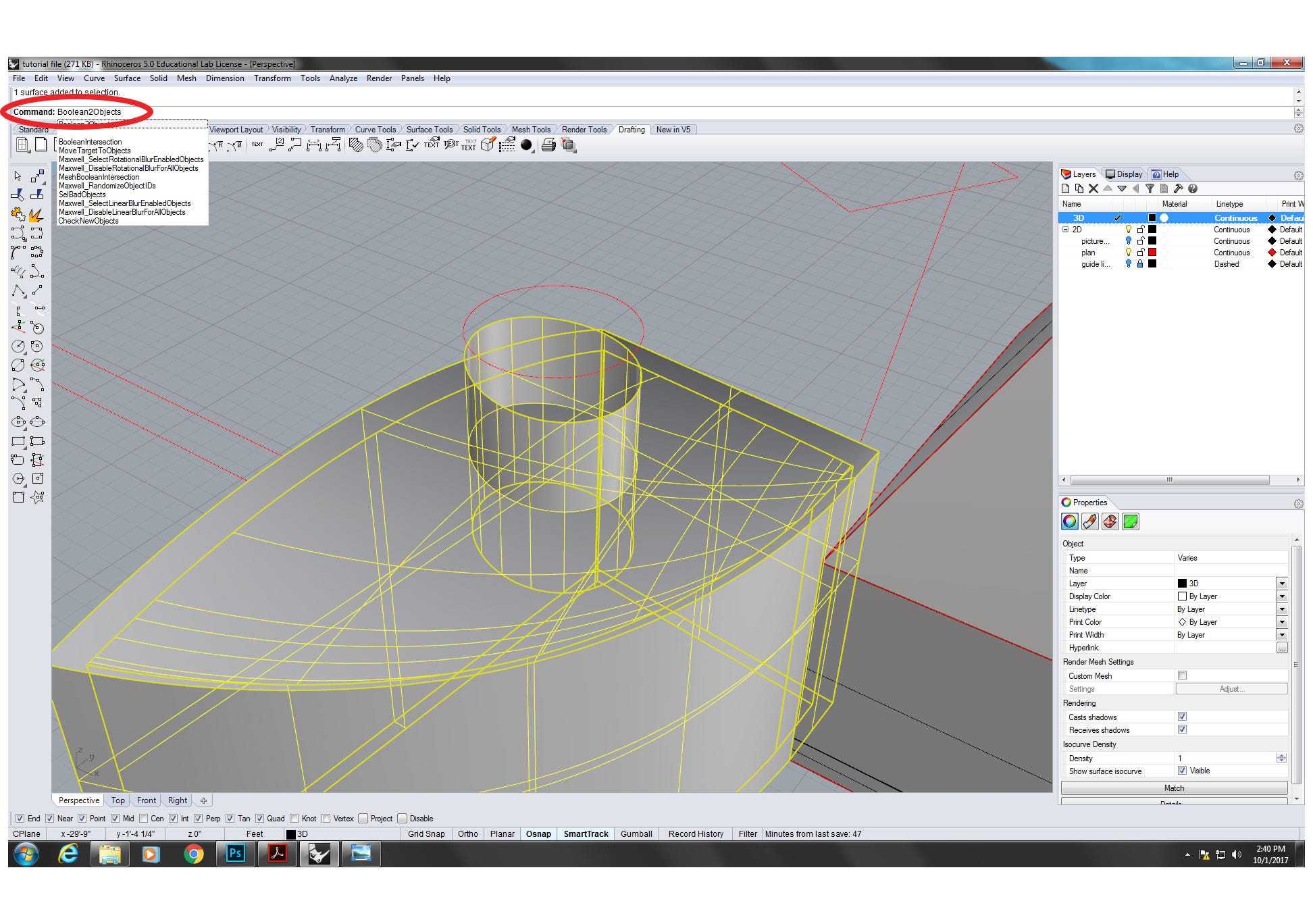
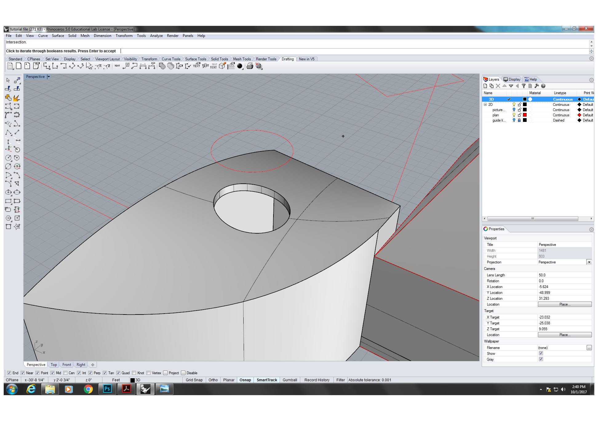
4.half dozen For the opening (window) on the curving face up, nosotros can project a geometry on the face then employ boolean options. Describe a circle and move it vertically above the curving rooftop of the building. Blazon in "project" command and follow the commands. Then select the projected circle, using "ExtrudeCrv" command to add thickness on both sides of the circle ("BothSides=Yes"). The last step is selecting both extruded circle and the building object, typing in "Boolean2Objects" then selecting "Intersection" option to create the opening on the curving rooftop.
Source: https://medium.com/dpro/using-2d-to-3d-method-to-create-solid-3d-objects-and-openings-in-rhino-29bf20223465
0 Response to "2d drawing into 3d modeling blueprints"
Post a Comment